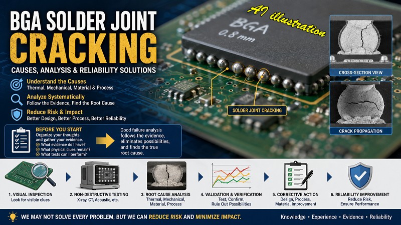
BGA solder joint cracking is one of the most challenging issues I’ve encountered throughout my career in electronics manufacturing. It’s also one of the topics that comes up most often whenever engineers discuss product reliability. Even today, there is still no universal solution that can completely eliminate BGA solder joint failures or the functional issues they cause.
While we may not be able to solve every BGA reliability problem, we can certainly reduce the risk and minimize the impact. That’s why Workingbear has gathered this collection of articles on component detachment and BGA solder joint cracking. I hope these resources will serve as a useful reference not only for myself, but also for anyone facing similar challenges.
I also hope this collection helps you revisit familiar concepts, learn from past experiences, and perhaps discover new ideas for solving your own reliability problems.
Before diving into BGA failure analysis, Workingbear recommends starting with the article “How to Begin Analyzing Field Returns and BGA Failures.” Before searching for the root cause, take a step back and organize your thoughts. Ask yourself: What evidence do I have? What physical clues have been preserved? What tests can I perform to verify my hypotheses? Effective failure analysis is all about following the evidence, eliminating possibilities one by one, and narrowing the problem down to its true root cause.
BGA Solder Joint Cracking: A Practical Guide
- 影片:BGA 回流焊焊接過程
- BGA焊接同時發生空焊及短路可能的原因
- 用數據比較OSP及ENIG表面處理電路板之焊接焊錫焊點強度
- How to Determine Whether Underfill is Needed for BGA?
- BGA Failure Analysis: Manufacturing Issue or Design Flaw?
- Why Burn/In(B/I) still cannot screen out the DDR soldering fail?
- Does PCB Solder Mask Misalignment Lead to BGA Soldering Defects?
- Both solder joint bridging and open solder joint happen at same BGA?
- Does the Gold Thickness in ENIG PCBs Affect Component Detachment?
- Inspection Methods for BGA Solder Ball Wettability and Soldering Defects
- NWO (Non-Wet-Open) Defect in BGA Soldering: Causes and Possible Solutions
- Can Increasing Solder Paste Volume Improve BGA Soldering Defects Such as HIP?
- What is HIP/HoP? Uncovering the Causes of Head-in-Pillow Defects in SMT Reflow
- [Case Study] BGA Solder Ball Cracking: Strain Gauge Analysis and Design Improvement
- Component Drop-Off on PCBs: How to Analyze, Troubleshoot, and Identify the Root Cause
- Top ENIG PCB Issues: Black Pad and Phosphorus-Rich Layers Explained with Prevention Tips
- How PCB S/M and Silkscreen Thickness Can Mess with Solder Paste Volume and Even Cause BGA Shorts!
- How to Analyze Returned Electronic Products and BGA Failures: A Practical Step-by-Step Troubleshooting Guide
How to Check for Cracks in BGA Solder Joints

If you want to determine whether a BGA solder ball has cracked, it is recommended to start with non-destructive inspection methods and use destructive methods, such as the Red Dye Test and cross-sectioning, only as a final confirmation.
Common non-destructive inspection methods include 2D X-ray. Ideally, use an X-ray system that allows you to tilt the inspection angle. If the machine does not have this function, you can try manually changing the angle. Even better, use 3D X-ray CT scanning. However, CT scanning is relatively slow, so it is better to first identify the suspected solder balls before performing a CT scan to save time.
Another option is to use a fiber-optic scope for inspection. However, a fiber-optic scope can generally only reach the outermost one or two rows of solder balls. If other components are blocking the view, its effectiveness can be quite limited. Still, it is better than having no inspection method at all!
- Using 2D X-Ray to Diagnose BGA Solder Void Issues
- How to Use 2D X-Ray to Identify BGA Issues like Non-Wetting, Cold Solder, and HIP or NWO
- 3D CT X-Ray Non-Destructive 3D Tomography Analysis for PCBA and BGA Failures
How to Analyze BGA Solder Joint Cracks: Red Dye, EDX, Cross-Sectioning, SEM, and IMC
- Red Dye Penetration Test to check for BGA solder joint cracking
- BGA Red Dye Penetration Test: Acceptance Criteria for Cracks and Voids
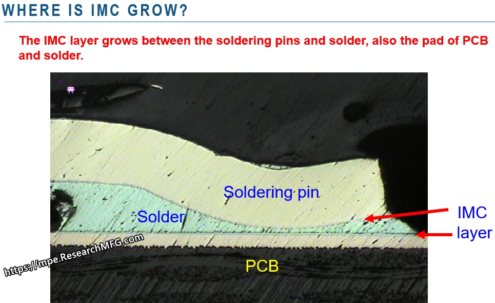
- What is IMC (Intermetallic Compound) in the electronic manufacturing industry?
- BGA Solder Ball Crack Analysis Using the Red Dye Test | Types and Failure Patterns
- Concept Clarification: IMC Layer Fracture Despite the Formation of Effective Solder Joints
- BGA Cross-Section Analysis: How to Evaluate Solder Joint Quality and Identify Common Defects
- BGA Solder Ball Crack Analysis: How to Identify the Root Cause Using the Red Dye Penetration Test
- How to Read a BGA Red Dye Penetration Test Report: What the Results Really Mean and How to Interpret Them
- What is IMC (Intermetallic Compound)? How does IMC relate to PCB solder joint strength? Are there IPC standards for IMC thickness?
Potential Solutions for BGA Solder Joint Cracking

- 實驗比較SMD與NSMD焊墊設計推球及拉力測試對BGA錫裂的影響
- How to Determine Whether Underfill is Needed for BGA?
- Underfill Techniques for Enhanced BGA and CSP Assembly
- Improve BGA solderability by partial increase solder paste volume
- How to Strengthen BGA Solder Joints Through Design to Prevent Cracking
- Preventing BGA Solder Joint Cracking: Strengthening Design from the Source
- Copper Defined vs. Solder Mask Defined pad design for BGA soldering strength
- BGA Solder Ball Crack Analysis Using the Red Dye Test | Types and Failure Patterns
- Preventing Solder Cracks in BGA Designs: Strengthening Tips from the Design End
- Should BGA Pads Be Designed as SMD or NSMD? Pros, Cons, and Drop-Test Performance
- Differences, advantages, disadvantages, and recommendations for SMD and NSMD pad designs
Myth: Component Drop-Off or Solder Cracking Is Always an SMT Process Problem
“Stress > Bonding-force”
is the root cause of electronic components drop from the PCB and solder crack.
- Why BGA soldering ball always crack(1)? Stress > bonding-force
- Why BGA soldering ball always crack(2)? The composition of PCBA bonding-force
- Why BGA soldering ball always crack(3)? IMC layer growth is a certain result to form the soldering joints
- Why BGA soldering ball always crack(4)? Using “copper” base material as the surface finish for PCB
- Why BGA soldering ball always crack(5)? Increase the contact area of solder to increase its strength
- Why BGA soldering ball always crack(6)? The recommendation of BGA pad design from Workingbear
- Why BGA soldering ball always crack(7)? The Bonding force between solder pad of copper foil and PCB substrate
- Why BGA soldering ball always crack(8)? Increase PCB stiffness to resist stress and avoid board bending
- Why BGA soldering ball always crack(9)? Increase the resistance of components to stress
- Why BGA soldering ball always crack(10)? Reduce the impact of PCB bending through the mechanism design change
- Why BGA soldering ball always crack(11)? Stress is the Biggest Culprit in Causing BGA Solder Joint Cracks
- Why BGA soldering ball always crack(12)? Manufacturing Processes That May Generate Significant Stress
- Why BGA soldering ball always crack(13)? Usage Environment is the Biggest Challenge of Stress Sources


Leave a Reply