Reducing the Impact of Stress on PCB Deformation through Mechanism Design
In earlier sections, WorkingBear briefly mentioned the possible solution by changing mechanism design to address the problem of solder cracking. One such approach involves replacing the SMDs (surface mount devices) that are prone to falling off with HTDs (through hole devices). This modification can significantly improve the strength of solder joints.
In this article, WorkingBear systematically summarizes these concepts for reference:
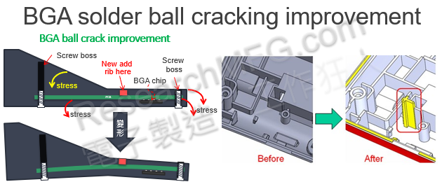
1. Enhance the material stiffness of mechanisms to prevent PCB from deformation
For example, changing the plastic casing material to metal can enhance its ability to resist external impacts. Alternatively, even without changing the casing material, ribs can be added to the surface under stress to reinforce its ability to resist deformation.
Some people also use one-piece (Integrally) formed shielding cans to cover BGA components that are prone to solder cracking to increase their strength.
However, Workingbear does not recommend this one-piece shielding cans design since the components under the shielding cans are hard to be reworked and repaired. Besides, the strength of the shielding can mainly relies on the soldering joint. If the soldering joint cannot withstand the stress impact then it will crack all the way to the BGA balls.
2. Using mechanisms to support the areas of PCB that are easy to bend or warp to reduce the amount of deformation of PCB
WorkingBear presented a case study earlier, wherein a pillar was introduced between the front and rear casings to provide support to the PCB and minimize the impact stress-induced deformation that occurs when the product drops from a height. The case study was highly successful, and it was emulated by other projects as well. However, as there was no additional space on the board, the pillar was placed on a shielding can, which was ineffective in minimizing the board deformation since the shielding can was hollow and could not exert any force.

Related reading: [Case Study] Improving BGA Solder Ball Cracking Using Strain Gauges to Confirm the Effect of Mechanism Design Changes
3. Reducing Circuit Board Impact with Buffer Materials
The approach of using buffer materials to secure PC boards and minimize deformation caused by external forces may not be suitable for models that are fully screwed onto the board. Instead, it may be more appropriate to attach a fixed screw on one side of the board and utilize buffer materials to secure the board on the other side. This method can act as a buffer against external forces, reducing the amount of deformation of the board when the casing experiences an impact.
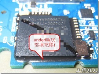
4. Using BGA underfill to enhance solder joint resistance to impact stress
 “Underfill” was originally designed for use in flip chip packaging to enhance its reliability, using a process and adhesive to protect against the impact of differences in thermal expansion coefficients between the chip and substrate, which can cause micro-gaps affecting chip performance during thermal cycling. Later, with the rise of BGA packaging, many CPUs began to use BGA packaging. However, due to the technology available at the time, BGAs actually had a certain thickness, and as the computing power of CPUs increased, the size of BGAs also became larger and heavier. This weight was very unfavorable for the gravitational impact of product drops. Therefore, in order to ensure product quality, many early BGA packages had underfill adhesive injected into the bottom to strengthen their surface quality when dropped.
 As manufacturing processes have advanced, most BGA packages are now smaller and the weight impact during drops is no longer the most sensitive factor. However, as electronic products continue to become smaller, the thickness of printed circuit boards is getting thinner. Consequently, the demand for flexibility and resistance to bending in electronic products is increasing. Unfortunately, solder joints based on “tin” are actually very prone to failure from bending. Although “Underfill” can provide good short-term stress resistance in drop impact testing, it cannot withstand long-term bending stress on printed circuit boards.
Article series :
- Why BGA soldering ball always crack(1)? Stress > bonding-force
- Why BGA soldering ball always crack(2)? The composition of PCBA bonding-force
- Why BGA soldering ball always crack(5)? Increase the contact area of solder to increase its strength
- Why BGA soldering ball always crack(6)? The recommendation of BGA pad design from Workingbear
- Why BGA soldering ball always crack(7)? The Bonding force between solder pad of copper foil and PCB substrate
- Why BGA soldering ball always crack(8)? Increase PCB stiffness to resist stress and avoid board bending
- Why BGA soldering ball always crack(9)? Increase the resistance of components to stress
- Why BGA soldering ball always crack(11)? Stress is the Biggest Culprit in Causing BGA Solder Joint Cracks
- Why BGA soldering ball always crack(12)? Manufacturing Processes That May Generate Significant Stress
- Why BGA soldering ball always crack(13)? Usage Environment is the Biggest Challenge of Stress Sources
Related article:
Increase solder paste volume will improve the MLCC capacitor broken?


Leave a Reply