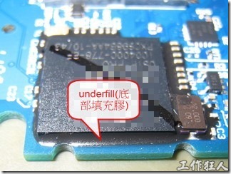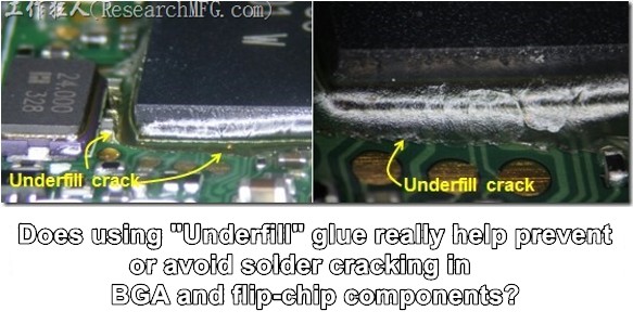
“Underfill” is a process and adhesive originally designed for use with flip-chip devices to enhance the mechanical strength of their solder joints and improve their reliability.
Flip-chips made of silicon material have a much lower coefficient of thermal expansion (CTE) than typical PCB materials. As a result, temperature cycling tests often cause relative displacement, leading to mechanical fatigue and problems such as solder joint detachment or cracking. Later, this Underfill technology was also widely used under some BGA packages to improve their reliability when soldered onto the PCB and to prevent them from falling or dropping.
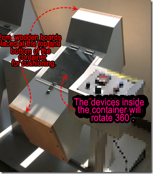
The material used for Underfill is usually epoxy polymer with significant amounts of filler, which uses the principle of capillary action to apply the epoxy to the edge of the chip already soldered to the PCB, allowing it to automatically penetrate to the bottom of the flip chip or BGA before being heated and cured. Because it effectively improves the mechanical strength of the solder joints, it can extend the lifespan of the chip. Therefore, it is mostly used in the PCB design of handheld devices, such as mobile phones, as handheld devices must pass rigorous drop and tumble tests, and many BGA solder joints cannot withstand such harsh testing conditions, especially on boards with ENIG surface treatment.
 The step of adding Underfill is usually arranged after the printed circuit board assembly (PCBA) is completed, that is, after completing SMT, wave soldering, hand soldering of parts, and fully passing the electrical test to ensure that all functions of the board are working correctly. This is because once underfill is applied, it becomes very difficult to repair or rework the device.
After adding the Underfill glue, it needs to be baked at high temperature to accelerate the curing time of the epoxy resin. This can ensure that the Underfill under the devices truly cured. Although epoxy resin can also cure slowly at room temperature, it takes at least 24 hours or more depending on the length of time it is exposed to air. Some epoxy resins also contain metal element additives. When selecting, attention must be paid to the surface impedance in liquid and solid states, otherwise there is a chance of current leakage.
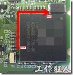
When adding the Underfill glue, generally only an L-shaped path is filled on the adjacent sides of the device.
Here are some steps for using Loctite 3536 to operate Underfill, for reference:
-
Loctite 3536 glue must be stored at low temperature (Loctite requires a temperature between 2℃ and 8℃). Before operation, it must be returned to room temperature for at least 1 hour before operation.
-
The printed circuit board to be underfilled needs to be preheated to 70℃.
-
Start the first time of Loctite 3536 glue for the BGA component along the L-shaped path at the edge of the BGA.

-
Wait for about 30-60 seconds for the Loctite 3536 glue to penetrate the bottom of the BGA body.
-
Make the second time of Loctite 3536 glue along the L-shaped path for the BGA component. The amount of glue should be slightly less than the first time. Wait for about 60 seconds to observe whether the black glue has spread around the BGA and formed a slope to cover the BGA. (The purpose of this is to ensure that there are minimal bubbles or voids under the BGA body.)
-
After confirming that the Underfill is correct, put the filled board into the oven and bake it at 130℃ for 20 minutes. (Loctite does not recommend baking at a temperature above 140℃.)
-
After baking, check whether the appearance of the Underfill glue is black and shiny, and lightly touch it with your fingernail to see if it feels smooth and hard.
The article translate from Underfill(底部填充劑)的目的與操作程序 | 電子製造,工作狂人(ResearchMFG)
Related Articles:


Leave a Reply