The Red Dye Penetration Test also known as Red Dye, is a technique used to inspect for surface-mount technology (SMT) defects such as voids or micro-cracks in the soldering of electronic components. It is a destructive test typically used on the SMT of printed circuit board (PCB) assemblies, and can assist engineers in verifying the quality of electronic component soldering.
Because the Red Dye test is a destructive experiment, it is typically only used on assembled PCBs (printed circuit boards) that cannot be inspected for issues using other non-destructive methods. Additionally, it is almost exclusively used for analyzing ICs (integrated circuits) with BGA (Ball Grid Array) packaging because the solder joints are located beneath the component and cannot be visually inspected using optical instruments.
Actually, the Red Dye Penetration Test is kind of Dye Penetrant Inspection (DP), also called Liquid Penetrate Inspection (LPI) or Penetrant Testing (PT). This inspection method is widely used and inexpensive, and is used to detect surface-breaking defects in all non-porous materials, including metals, plastics, and ceramics.
Although the penetrant can be applied to both ferrous and non-ferrous materials, magnetic-particle inspection is often used for ferrous components due to its ability to detect subsurface defects. LPI is commonly used to identify surface defects such as hairline cracks, surface porosity, leaks in new products, and fatigue cracks in in-service components, such as those found in castings, forgings, and welds.
In the last few years, there have been significant advances in 3D CT X-Ray inspection technology, which has the potential to detect solder joint fractures using X-ray optics. However, the resolution of this technology is still inadequate, and the scanning process takes too long. Therefore, further enhancements are necessary to improve its performance and capabilities.
The Red Dye test is often performed to gain a better understanding of faulty soldering in a electronic product. It can serve as a reference for improving quality in future production or clarify responsibility for product defects.
Clarification on the Concept of Red Dye Test:
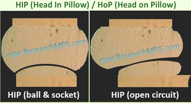
First, it is crucial to understand that the purpose of the Red Dye Test is to utilize the characteristic of red dye penetrating cracks to identify issues with BGA solder ball cracking or HIP(Head-in-Pillow) or call HoP (Head-of-Pillow) defect.
Following the heating and soldering process, there is a layer of flux residue present around the BGA solder balls, although it may not be visible to many individuals. In the case of water-washed solder paste, the flux residue may be eliminated during the process. However, in modern times, most solder pastes are no-clean, so flux residue is always left behind.
This flux residue may obstruct the red dye from penetrating possible cracks in the BGA solder balls. Hence, it is critical to remove the flux residue around the balls effectively. The larger the BGA size or the smaller the pitch between the solder balls, the more important it is to ensure that the flux residue is entirely removed. Soaking the BGA in a solvent for a period of time before utilizing ultrasonic agitation to clean it is usually recommended.
When commencing the red dye test, it is suggested to position the BGA horizontally and apply the red dye to adjacent sides of the BGA body in an L-shaped path. This approach allows the dye to infiltrate underneath the BGA naturally and flow out of the other two sides without dye. As a result, it can effectively ensure that the dye penetrates into all corners underneath the BGA and avoids the shadow effect. Placing the BGA vertically to accelerate red dye penetration is not recommended. If the shadow effect needs to be avoided permanently, the entire board can be submerged in red dye and then ultrasonically agitated, or vacuum can be used.
Methodology for Red Dye Test Made from a Homemade Process
 The procedure commences with the utilization of a solvent to eliminate the residual flux underneath the BGA component, a crucial step that many beginners frequently disregard.
Next, inject a red dye with appropriate viscosity into underneath the suspected BGA or CSP (Chip Scale Package) component with soldering defects. It is recommended to inject the red dye slowly from one end (preferably the right angle) while tilting the board slightly to prevent the formation of bubbles. This ensures that the red dye penetrates adequately by continuously injecting it until the perimeter of the component is filled. It is suggested to inject a little more red dye rather than less.
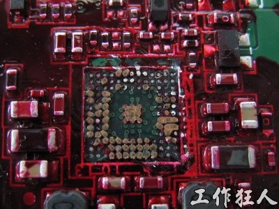
After injection, allow the board to stand or bake horizontally until the red dye is entirely dry. Then, using a tool, the BGA can be directly removed from the PCB without damaging the BGA body. For a DIY approach, a slotted screwdriver is usually employed to lift the BGA, while a more rigorous operation should use AB glue or epoxy resin to attach it to the BGA body and then use a puller to remove it.
Note: Heating and baking temperature should not exceed the temperature at which the solder re-melts.
Workingbear believes this method is similar to how plumbers or pipeline workers detect leaks by pouring a colored solvent and looking for colored water to identify the source of the leak.
A Robust Laboratory Method for Red Dye Testing
For a professional method of red ink testing, suspected soldering issues on the assembled circuit board should be cut out and the flux should be removed with a solvent. Then, the entire board can be immersed in red ink, or if the board is small enough, it can be placed in the red ink solution along with an ultrasonic cleaner for a period of time. This will allow the red ink to penetrate all the cracks evenly. Afterward, the board should be taken out and baked. The purpose of baking is only to dry the red ink, so high temperatures are not necessary. The sample should then be clamped into a fixture, and the BGA body should be pulled away from the circuit board before being observed under a high-magnification microscope for staining.
Nowadays, the utilization of ultrasonic cleaners is less common due to concerns about the solder joints that has not yet broken was damaged. Therefore, selecting the appropriate red dye material is crucial to ensure that it can penetrate the cracks adequately and stain them effectively. Furthermore, some experts recommend vacuuming the sample after immersion to ensure the thorough penetration of red ink into every gap.
Inspect BGA Solder Balls for Breaks, Voids, and other Defects Under a Microscope

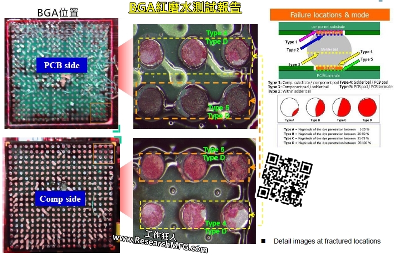
Observe the solder pads and IC solder balls that have been lifted to check for red dye staining. Evidence of poor soldering, such as cracks, cold solder, and voids, should be noticeable as traces of red dye penetrating the fracture surfaces of the solder balls. It is recommended to observe from multiple angles to avoid misjudgment caused by lighting. Use a BGA solder joint distribution table to record the status of the solder balls.
The principle of the red dye experiment is to use the penetrating property of liquid to penetrate all solder joints to determine if the soldering is intact. For a typical BGA IC, both ends of the solder balls should be connected separately to the PCB and the substrate of BGA. If red dye stains appear in the soldering position, it indicates that there are gaps or solder joint fractures or other problems. The rough surface of the solder joint fracture can be used to determine whether it is an original poor soldering or a fracture caused by improper use after installation.
Generally, the surface of a cold solder, void or poor soldering is smooth because solder has strong cohesion, but there are exceptions. For example, poor soldering caused by oxidation or foreign material contamination can also form a rough surface. As for the surface of a fracture caused by improper use, it shows a more irregular sharp concave and convex surface, but if it is a fracture caused by long-term use, a smooth surface may also appear.

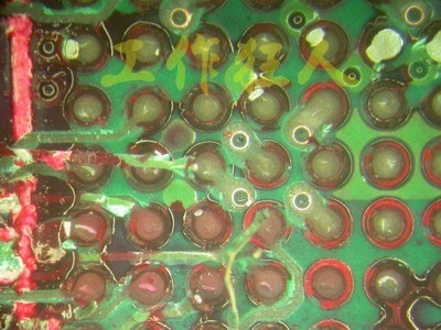
The image above shows the results of a Red Dye Penetration Test, where it is clear that many of the BGA solder balls in the lower left corner are stained with red dye, indicating the presence of voids or fractures in those solder balls.
As for the acceptance criteria for the red dye penetration test, please refer to another article: Acceptance criteria for red dye penetration test analysis.
The article translate from 簡介用紅墨水試驗 (Red Dye Penetration Test)查看BGA焊錫有否破裂
Related Articles:


Leave a Reply