

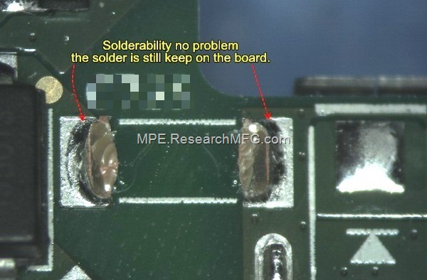
Recently, Workingbear received a complaint from R&D asking us to increase the solder paste volume on the MLCC (Multilayer Ceramic Capacitor) component pads to improve a capacitor cracking issue. R&D said they had verified that the capacitor footprint in the PCB design was correct and followed the manufacturer’s design guidelines. However, they suspected that there was not enough solder paste to form a proper heel fillet on the capacitor terminals. The question was: Could the insufficient solder paste volume be causing the solder joint to crack?
Well, Workingbear reviewed the photos provided by R&D and found that the MLCC was more likely damaged by mechanical stress caused by PCB warpage. Instead of asking the SMT process to increase the solder paste volume, I would recommend finding out what caused the PCB to bend and ultimately crack the capacitor.
The solder fillets looked good, and there were no obvious signs of soldering-related damage in the photos. More importantly, the crack started from the edge of the MLCC body rather than through the solder joint itself. Based on my experience, I really don’t think increasing the solder paste volume would improve this type of capacitor cracking.
 Workingbear strongly suspected that the stress was coming from outside the product. For example, a drop impact could cause the PCB to bend, or inserting and removing a cable could apply a twisting force to the PCB. This product uses a 1.2 mm thick PCB, and a USB Type-A connector is located very close to the damaged capacitor. Plugging and unplugging a USB cable can apply both pushing and twisting forces to the PCB, making it relatively easy to bend the board.
After several rounds of discussion, I eventually received confirmation that the capacitor failure occurred during the tumble test.
By the way, my experience tells me that simply increasing the solder paste volume does not do much to improve this type of MLCC cracking. If we look closely at the damaged capacitor, the crack is located outside the soldered area. This means that no matter how much additional solder paste is applied, the solder joint cannot extend beyond the heel of the pad and reinforce the cracked area.
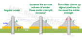
In fact, adding more solder paste could potentially make the situation worse. Excessive solder can increase the mechanical stress on the MLCC body, especially if the additional solder causes the component to sit higher above the PCB. This can increase the leverage on the component and make it more susceptible to bending stress.
Based on my experience, the following solutions may help prevent this type of MLCC cracking:
1. Stengten the PCB
Increase board thickness or apply high TG material will enhance the board strength to give more robust to against stress.Increasing the PCB thickness or using a higher-Tg material can improve the board’s mechanical strength and make it more resistant to bending and external stress.
2. Add a mechanical support structure
It is better to first use strain gauges to measure the magnitude, location, and direction of the mechanical stress. Based on the measurement results, a mechanical support or fixture can then be designed to hold the PCB and prevent excessive bending during tumble testing or product drop tests.
3. Select an MLCC with longer solder termination pads
Different capacitor manufacturers may use different termination and pad dimensions even for capacitors of the same package size. Based on Workingbear’s experience, an MLCC with longer solder terminations generally has better resistance to mechanical stress.
One reason is that longer terminations can reduce the unsupported gap between the capacitor body and the PCB pad, which helps reduce the stress concentration caused by the lever effect when the PCB bends.

Related posts:
- Why thinner PCB will need carrier for reflow process?
- What is Step-up & Step-down Stencil? Selective Solder Paste
- The benefit to use shielding clips to instead of shielding frame



Leave a Reply