Do you know what are the SMD (Solder Mask Defined) and NSMD (Non-Solder Mask Defined) land pattern pads? Any difference between SMD and NSMD pads? What are the advantages and disadvantages for them? What are the design recommendations for them?
Many people in the electronics industry may have heard of “SMD (Surface Mount Device)” of electronic components” and “SMT (Surface Mount Technology)” of soldering technology, but may not know what NSMD is. In fact, SMD and NSMD referred to here are the exposed copper pads or land pattern layout design seen on the PCB. This kind of small detail in PCB pad design was not even noticed by anyone in the past, but has become increasingly important due to the trend of electronic components becoming smaller. Because it affects the quality of solder and the strength of soldering.
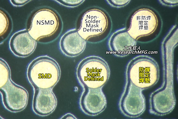
So what exactly are SMD (Solder Mask Defined) and NSMD (Non-Solder Mask Defined) pad designs?
Nowadays, PCB pads and traces are basically made of copper foil, but we do not expose all the copper foil when designing PCBs. We only expose the pads that need to be contacted or soldered to avoid possible problems such as moisture causing short in the future. At this point, we generally use a so-called “solder mask” to cover the copper foil that does not need to be exposed. Therefore, the precision and ability of solder mask printing become quite important relative to small pads.

What is the SMD (Solder Mask Defined) pad designed?

The SMD (Solder-Mask Defined Pad Design) is a term used to describe a land pattern design of PCB where the solder-mask (green ink) is applied to cover a larger area of copper foil, and the copper foil is then exposed at the opening of the solder-mask to form the pad. Because the size of the pad depends on the size of the solder-mask opening, it is called a solder-mask defined pad design.
What is the NSMD (Non-Solder Mask Defined) pad designed? Also call “Copper Defined” pad?

The NSMD (Non-Solder Mask Defined) pad design or Copper Defined pad is a design where the copper foil is made smaller than the opening of the solder mask, creating a pad size that is essentially determined by the copper size, similar to an island in a lake. Therefore, it is called a copper defined pad design or non-solder mask defined pad design.
What are the advantages and disadvantages of SMD (Solder Mask Defined) and NSMD (Non-Solder Mask Defined) pad designs? What kind of pad design is the best for BGA soldering to solve the cracking issue?
Well, if you have these questions, you are probably dealing with issues of solder ball cracking or component fall down, especially with BGA solder ball cracking. I can tell you clearly that there is no pad design that can completely solve the problem of BGA solder ball cracking. If you like to solve this problem thoroughly, you need to start with the mechanical design. I know many RDs only want to rely on pad design or strengthening solder joint to solve BGA solder ball cracking. Workingbear’s company has indeed required EMS (Electronics Manufacturing Service) factory to try many methods to fix it, but the results are very limited. In the end, the improvement was mostly achieved by improving the stress impact through mechanical design change. Both SMD and NSMD pad designs have their own advantages and disadvantages, and they have their own strengths in terms of solder strength and bonding with the PCB. Therefore, it really can’t be said which pad design is better. When your company decides which pad design to use, it is recommended to consider the size and spacing of the BGA solder balls. Before comparing these designs, we need to assume that the exposed copper area required by SMD and NSMD pad designs is the same size, otherwise the comparison would not be meaningful.
The advantages of SMD (Solder Mask Defined) pad designed:
The actual copper size of SMD pads is relatively larger than NSMD, and the area around the pads is covered with solder mask to enhance the bonding strength between the pads and FR4 of PCB. This makes the pads less likely to detach during repairs or rework.
The disadvantages of SMD (Solder Mask Defined) pad designed:
The solder joint strength of SMD pads is relatively weaker because the solderable area is smaller as compare with NSMD, and the solder mask covers the surrounding pad. The solder mask will change its size, expand during the high-temperature reflow process, and contract during colling. This will affect the wetting quality of the solder joint at the interface between the pad and the solder mask.Besides, this also create some uneven soldering at the junction, which cannot effectively disperse stress, especially in environments with repeated thermal cycling or long-term mechanical vibration. These areas of stress concentration are prone to fatigue cracking.
Under stress, SMD pads are more likely to crack on the surface, especially at the IMC layer.
Additionally, the reduced spacing between the pads makes PCB layout more difficult.
The advantages of NSMD (Non-Solder Mask Defined) pad designed:
Because the soldering pad of NSMD is independent copper foil, during the reflow process, not only the top surface of pad , but also the surrounding vertical sides around the edge of pad will be wetted, forming a solder fillet. This helps to effectively disperse stress. Of course, areas with traces are an exception, relatively speaking, the area where solder wetted on NSMD is larger, so the soldering strength is relatively better.
The actual area of the copper foil in NSMD is relatively small as compare with SMD, making it easier for layout engineers to route traces between the BGA solder pads easily.
The disadvantages of NSMD (Non-Solder Mask Defined) pad designed:
The bonding force between the solder pad and FR4 of PCB is relatively poor because the actual area of the copper foil is small. During repair or rework, the solder pad is more likely to come off due to repeated heating.
The entire solder pad is easy to lift off under stress.
Flux and solder beads are more likely to remain in areas not covered by solder-mask because those areas is rough.
The size of the solder pad is not consistent when actually produced because there are traces coming in and out of the pad. Different trace widths and numbers result in different exposed copper (solder pad) areas, and the same amount of solder paste used on different solder pad sizes can cause poor soldering.
However, in practice, people rarely increase or decrease the amount of solder paste added for these incoming and outgoing lines because it is cumbersome to calculate the area of each solder pad one by one. Moreover, the main purpose of the solder paste under the BGA is to connect the BGA’s solder balls. In other words, the difference in the amount of solder paste used does not affect the overall amount of solder on the BGA solder balls too much. Unless there is a soldering issues or other problem, such as HIP/HoP issues or solder joint breaking, nobody will want to modify the stencil aperture size to make up for the amount of solder.
Of course, this disadvantage can be improved by modifying the shape of the solder mask, but it requires manual adjustment, which takes time and visual acuity. Many layout engineer are unwilling to spend this time. People may ask the PCB supplier to make the modification but different supplier can yield different results. Another option is to manually modify the aperture size of the stencil in each solder pad to compensate for the amount of solder paste, but the best method is to start with design changes, such as having consistent solder pad sizes in Gerber files.
What is the timing for using SMD (Solder Mask Defined) and NSMD (Non-Solder Mask Defined) pad designs?
Refers to the above image, the outline of the solder pad designed for the SMD pad designs is usually more complete because it is less affected by the trace routing. It is recommended to use SMD pad designs for small chips and fine-pitch components, such as resistors, capacitors, inductors, TVS diodes, etc., especially for components 0201 and 01005 and or smaller. Otherwise, tombstone defect may occur during soldering.
The reason why WorkingBear do not recommend using NSMD for these small components is that most solder pads are designed to connect with other traces or routing. This is similar to the example of lake island that needs bridge to connect, so that electronic signals can be transmitted. Imagine if a bridge takes up 1/4 or 1/2 of circumference of the island, These bridges can be viewed as copper foils of the trace routing. This will cause the shape of the solder pad to deform and most of the trace routing on the pad are at least one in and at most, one pad can be connected to 3~4 trace outing. Therefore, the solder pad has almost become an SMD pad. When designing, the PCB layout engineer may not consider too much and the opening of the solder mask will also be relatively large to prevent solder bridging. This will cause the size of the solder pad on both ends of the same component to become different, and this difference may cause a difference in the amount of solder paste applied, leading to the tombstone defect.
For other chips with a size above 0603, whether SMD or NSMD is used has less impact on the solder. However, it is still helpful to try to make all pads on the same component the same size to improve the quality of soldering.
As for whether to use SMD or NSMD pad designs for BGA, WorkingBear recommend that you read the article series of “Why BGA soldering ball always crack(1)? Stress > bonding-force” before discussion.
After you read these articles about BGA solder ball cracking, you will find that WorkingBear strongly recommend using NSMD + plugged via for BGA pad designs. The conductive vias on the pads must be electroplated and filled with copper, and the pad size should be enlarged as much as possible. If it is not possible to apply this design to all pads of the BGA, at least the outermost row of pads should be designed this way.
Related Articles:


Leave a Reply