Working for manufacturer engineering couple years. Sharing the manufacturing experience, skill, DFx, design, and information. Be care of this blog is personal share and content may not be 100% correctly.
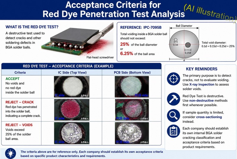
Figure: BGA Red Dye Penetration Test: Acceptance Criteria for Cracks and Voids
A reader asked Workingbear, “After performing a Red Dye Penetration / Red & Pry Test on a BGA, how should we determine the acceptance and rejection criteria?”
At first, this question really stumped Workingbear. The Red Dye Penetration Test is a destructive test, and its primary purpose is generally to check whether BGA solder balls have cracks or other soldering defects. Therefore, there is usually no formal acceptance criterion specifically for this test. The test can mainly be used to determine whether a solder ball has cracked.
After searching through various sources, I could not find any specific industry standard that defines acceptance criteria for Red Dye Penetration Test results. If we need a reference for establishing acceptance criteria, IPC-7095, Design and Assembly Process Implementation for BGAs, may provide some useful guidance, particularly Section 7.5.1.7, Process Control Criteria for Voids in Solder Balls.
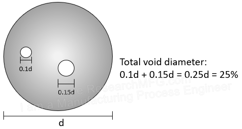
According to the updated requirements in IPC-7095B Section 7.5.1.7, the total voiding inside a BGA solder ball should not exceed 25% of the ball diameter or 6.25% of the ball area. Excessive voiding can increase the risk of non-wetting, solder joint failure, or solder cracking.
According to the updated requirements in IPC-7095B Section 7.5.1.7, the voiding criterion inside BGA solder balls has been standardized: the total voiding should not exceed 25% of the ball diameter or 6.25% of the ball area.
However, the above criterion is based on an X-ray image, while the Red Dye Penetration Test reveals defects after the solder ball is mechanically pulled apart. As a result, the voids revealed by the Red Dye Test may appear slightly smaller than those observed by X-ray, and some smaller voids may not be revealed at all. Therefore, some companies may choose to define their internal acceptance criteria slightly more strictly than the criteria specified in IPC-7095 Section 7.5.1.6. Ultimately, each company may need to establish its own acceptance criteria based on its specific product requirements.
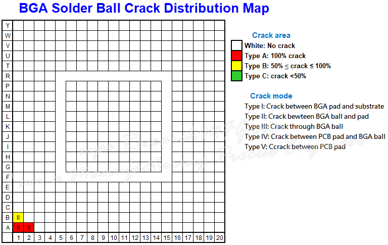
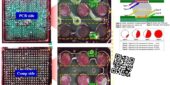
Figure: BGA Solder Ball Crack Distribution Record After the Red Dye Test
During a typical Red Dye Penetration Test, a BGA solder ball crack distribution map like the one shown above is used to record the dye penetration results on both the IC side and PCB side. The percentage of the voided area can also be recorded. Workingbear has seen some companies define their own acceptance criteria for Red Dye Penetration Test results as follows:
No solder ball or solder joint cracking is allowed. In other words, no red dye should be visible inside the solder ball.
The total voided area must not exceed 25% of the solder ball area.
IC side
PCB side
Accept No voids and no red dye inside the solder ball
Reject Red dye has penetrated into the solder ball, indicating a complety crack.
Reject Voids exceed 25% of the solder ball area
The information above is provided for reference only. Thanks to the contributors who provided the data.
Finally, Workingbear would like to offer a few reminders:
The primary purpose of the Red Dye Penetration Test is to determine whether a solder ball or solder joint has cracked. It is not particularly suitable as a standalone method for evaluating voids. X-ray inspection is recommended for evaluating solder voiding.
The Red Dye Penetration Test is destructive. Non-destructive inspection methods should be used first whenever possible.
If the number of available samples is limited, consider cross-sectioning instead.
Each company is advised to establish its own internal BGA solder cracking classification and acceptance criteria based on its specific product characteristics and requirements.








Leave a Reply