
In the assembly and soldering process of printed circuit boards (PCBs), we often hear engineers or lab reports mentioning the term “IMC.” But what exactly is IMC? What role does IMC play in the PCB assembly (PCBA) soldering process? Does it impact solder joint strength? People often comment on IMC being too thin or too thick, so what is a reasonable thickness for IMC?
Here, the WorkingBear has compiled some insights into the relationship between PCB solder joint strength and IMC for reference.
1. What is IMC?
 IMC stands for InterMetallic Compound in the electronic manufacturing industry.
IMC (Intermetallic Compound) is a chemical molecular. It’s not an alloy (note: some classify IMC as a type of alloy), nor is it pure metal.
Since IMC is a molecular composition resulting from a chemical reaction (IMC can also form under ambient temperature through diffusion, but the process is very slow), providing energy is necessary for its accelerated formation. This explains why solder paste needs heating during the soldering process. Moreover, in the solder paste composition, only pure tin (Sn) reacts with the copper base (e.g., OSP, I-Ag, I-Sn surface-finished PCB) or nickel base (ENIG surface-finished PCB) during intense heat, leading to the formation of a robust interfacial IMC.
2. Difference Between Alloy and Intermetallic Compound (IMC)
Intermetallic Compounds (IMCs) are compounds formed by “fixed proportions” of two or more metallic elements through a “chemical reaction,” resulting in a pure substance. Examples include Cu6Sn5、Ni3Sn4、AuSn4, and similar substances. (IMC can also form under ambient temperature through diffusion, but the process is very slow)
On the other hand, an alloy is a mixture of two or more metals with no fixed proportions; the ratios can be adjusted as needed. It simply involves uniformly blending different elements together.
In simpler terms, you can think of men and women mixed together as an alloy, while the child born from their union can be considered a compound.
3. Why “Solder Paste” Contains Other Metals?
Solder paste is a paste-like substance made by blending alloy particles, primarily consisting of tin, with a small amount of other metals, along with flux. Since pure tin has a high melting point of 232°C, making it impractical for general PCB assembly soldering (electronic components cannot withstand such high temperatures), it needs to be based on tin with the addition of other alloying agents to lower its melting point. This achieves the main goal of mass production and energy savings, with a secondary goal of improving solder joint toughness and strength using specific metals.
For instance, SAC305 is made primarily of tin with small amounts of silver and copper, bringing its eutectic melting point down to 217°C. Another solder paste, SCNi, incorporates tin with small amounts of copper and nickel, resulting in a eutectic melting point of 227°C. It’s an intriguing topic—why do metals with originally high melting points significantly reduce their “eutectic melting point” when mixed in specific proportions? If you’re interested, you can refer to the tin-lead binary phase diagram for more information.
Further Reading: What purpose of alloy metal of Cu, Ag, Zn, Sb, Bi added to solder paste?
YouTube: What is IMC? Explain Alloy, Eutectic in detail
4. Chemical Formulas of IMC Compounds and Their Formation (Cu6Sn5 ,Ni3Sn4 ,Cu3Sn ,AuSn4 ,Ag3Sn ,PdSn4)
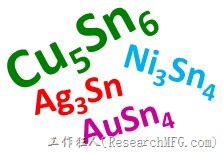 In the world of PCB assembly, you often come across chemical formulas like Cu6Sn5, Ni3Sn4, Cu3Sn, AuSn4, Ag3Sn, and PdSn4 related to IMC. But how do these formulas come about, and where do they form?
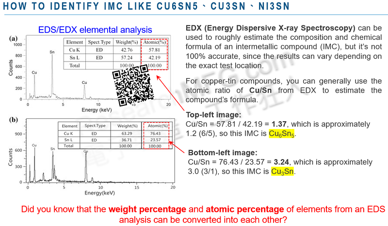
For copper-based PCBs with surface finished like OSP, I-Ag, I-Sn, HASL, and solder paste, the high-temperature reflow process in a reflow oven creates the beneficial Cu6Sn5 IMC compound. However, with aging or prolonged exposure to high temperatures in the reflow oven, Cu6Sn5 gradually evolves into the less favorable Cu3Sn.
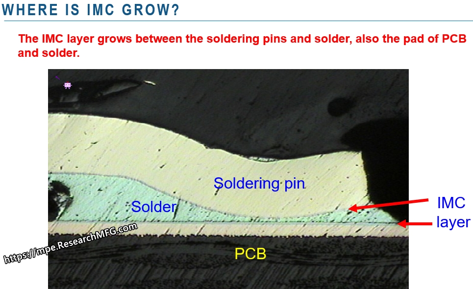
Cu6Sn5 primarily forms through the reaction of liquid Cu and Sn and grows initially between the copper base and solder. Cu3Sn, on the other hand, results from the solid-state reaction of the already formed Cu6Sn5 with Cu, usually occurring at the interface between Cu and Cu6Sn5.
For nickel-based PCBs with surface finished like ENIG, ENXG, and ENEPIG, the combination of high-temperature reflow and solder paste leads to the formation of the beneficial Ni3Sn4 IMC.
Moreover, gold (Au), silver (Ag), and palladium (Pd) can also form compounds like AuSn4, Ag3Sn, and PdSn4 with tin (Sn). However, these are wandering IMCs, and if they persist at the solder interface, they generally harm the solder joint’s strength. The primary role of gold and silver on the solder pad is to protect the underlying nickel and copper from rust when exposed to air. Thicker layers of gold and silver weaken the solder joint, but they shouldn’t be too thin, or they won’t effectively shield the underlying nickel or copper.
5. Strength of Various IMCs
-
A reminder: soldering is a chemical reaction.
-
Taking copper-based solder pads as an example, a good solder joint immediately forms the benign Cu6Sn5 IMC, which thickens over time and accumulated soldering heat.
-
In the aging process, the copper-based solder joint will also grow the malignant ε-phase (read Epsilon) Cu3Sn IMC on the original Cu6Sn5. Overall, copper-based solder joints have better strength and reliability than nickel-based ones, but their strength diminishes over time.
-
Nickel-based PCBs like electroless nickel immersion gold (ENIG) and electroplated nickel gold create the Ni3Sn4 intermetallic compound with solder paste. Thicker gold layers, however, result in thinner IMC formation at the solder joint. When gold hasn’t entirely diffused away, it may lead to gold embrittlement. Ni3Sn4 inherently has lower strength than Cu6Sn5.
| Name | Molecular Formulas |
Tin Content W% | Formation Process | Location | Color | Crystal Structure | Nature of IMC | Surface Energy |
|
η-phase |
Cu6Sn5 | 60% | Generated when high-temperature molten tin is soldered onto a clean copper surface. | Between the solder and pure tin interface. | White | Spherical organization | Essential for solder joint strength; benign IMC. | Very high |
|
ε-phase |
Cu3Sn | 30% | Gradually forms after soldering and subjected to high temperatures or extended aging. | Between Cu6Sn5 and the copper surface. | Gray | Columnar crystals | May lead to poor wetting or non-soldering; malignant IMC. | Lower, only half of Eta’s performance |
6. Is Thicker IMC Better? Any IPC Standards for IMC Thickness?
In reality, when it comes to Intermetallic Compound (IMC) thickness, it’s not a case of “the thicker, the better.” The key is to ensure that IMC grows uniformly. As time passes and heat accumulates, IMC tends to grow thicker. However, excessive thickness doesn’t necessarily mean better strength; in fact, it can make the structure more brittle. Think of IMC like the cement between bricks when building a wall. An appropriate thickness of cement binds the bricks together, but if it’s too thick, the structure becomes more prone to collapse (additional details are explained in the video).
The rate of IMC formation is generally proportional to the square of time and temperature (as illustrated in the video).
Moreover, the video suggests that the recommended IMC thickness falls in the range of 1 to 3 micrometers (µm). It’s important to note that this is just a suggestion. Understanding the principles of IMC formation reveals that there are no IPC industry standards dictating the thickness of IMC.
Check out the video explanation on “What is IMC?” (covering differences between alloy, eutectic, and intermetallic compounds, along with suggested IMC thickness).
This video provides insights into Intermetallic Compounds (IMC) – what they are and how they form.
YouTube: What is IMC? The role of IMC plays in the soldering
1 µm = 39.37 µin
1 µin = 0.0254 µm
1 mil = 25.4 µm
Related Posts:





Leave a Reply