Working for manufacturer engineering couple years. Sharing the manufacturing experience, skill, DFx, design, and information. Be care of this blog is personal share and content may not be 100% correctly.
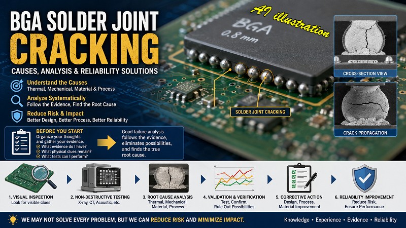
BGA solder joint cracking is one of the most challenging issues I’ve encountered throughout my career in electronics manufacturing. It’s also one of the topics that comes up most often whenever engineers discuss product reliability. Even today, there is still no universal solution that can completely eliminate BGA solder joint failures or the functional issues they cause.
While we may not be able to solve every BGA reliability problem, we can certainly reduce the risk and minimize the impact. That’s why Workingbear has gathered this collection of articles on component detachment and BGA solder joint cracking. I hope these resources will serve as a useful reference not only for myself, but also for anyone facing similar challenges.
I also hope this collection helps you revisit familiar concepts, learn from past experiences, and perhaps discover new ideas for solving your own reliability problems.
Before diving into BGA failure analysis, Workingbear recommends starting with the article “How to Begin Analyzing Field Returns and BGA Failures.” Before searching for the root cause, take a step back and organize your thoughts. Ask yourself: What evidence do I have? What physical clues have been preserved? What tests can I perform to verify my hypotheses? Effective failure analysis is all about following the evidence, eliminating possibilities one by one, and narrowing the problem down to its true root cause.
BGA Solder Joint Cracking: A Practical Guide
Figure: What is HIP/HoP? Uncovering the Causes of Head-in-Pillow Defects in SMT Reflow
If you want to determine whether a BGA solder ball has cracked, it is recommended to start with non-destructive inspection methods and use destructive methods, such as the Red Dye Test and cross-sectioning, only as a final confirmation.
Common non-destructive inspection methods include 2D X-ray. Ideally, use an X-ray system that allows you to tilt the inspection angle. If the machine does not have this function, you can try manually changing the angle. Even better, use 3D X-ray CT scanning. However, CT scanning is relatively slow, so it is better to first identify the suspected solder balls before performing a CT scan to save time.
Another option is to use a fiber-optic scope for inspection. However, a fiber-optic scope can generally only reach the outermost one or two rows of solder balls. If other components are blocking the view, its effectiveness can be quite limited. Still, it is better than having no inspection method at all!









Leave a Reply