Working for manufacturer engineering couple years. Sharing the manufacturing experience, skill, DFx, design, and information. Be care of this blog is personal share and content may not be 100% correctly.
Figure: OSP vs. ENIG: Which PCB Surface Finish Provides Stronger BGA Solder Joints?
This article uses experimental data to demonstrate that solder joints on OSP-finished PCBs can have higher strength than those on ENIG-finished PCBs. The results also confirm that the solder joint strength of OSP-finished boards deteriorates with aging. OSP performs better at low and medium shear speeds, but the difference becomes smaller at high shear speeds. This suggests that products using OSP-finished PCBs may become more susceptible to solder joint failures as they age in the field.
If you have worked in the SMT or PCB assembly industry for a while, you may have heard an expert or an experienced engineer say that OSP-finished PCBs provide stronger solder joints than ENIG-finished PCBs. A more technically accurate way to put it would be that solder joints on copper-based finishes are stronger than those on nickel-based finishes. However, not many people seem to have actual test data to show exactly how much stronger OSP is than ENIG.
Workingbear searched for various technical reports and eventually found an English-version paper published by Japan-based Nihon Superior around 2008, titled “Strength of Lead-Free BGA Spheres in High Speed Loading.” This report is relatively easy to understand, so I will use it as the primary reference to explain how OSP- and ENIG-finished solder joints withstand shear stress. I will also briefly discuss how SMD (Solder Mask Defined) pad design can affect the results.
With portable electronic devices becoming increasingly common, accidental drops are a frequent occurrence. To simulate these conditions, the report tested BGA solder balls attached to OSP- and ENIG-finished boards at different shear speeds and measured their fracture energy. Fracture energy was used as the basis for evaluating solder joint strength.
The test samples and conditions used in the report are listed below. Readers who are interested in the full details can search for the original report by its title online.
PCB surface finishes: OSP and ENIG (0.3 µm Ni / 0.03 µm Au)
Solder ball alloys: Sn-3.0Ag-0.5Cu (SAC305), Sn-0.7Cu-0.05Ni-0.006Ge, and 63Sn-37Pb
Shear speeds: 10, 100, 1,000, 2,000, and 4,000 mm/sec
The report used two test methods: a shear test and a pull test. However, Workingbear will focus only on the shear test results here. Readers interested in the pull test can refer to the original report online. The test shown on the left applies a lateral shear force to the BGA solder ball.
One important point to understand is that the report uses fracture energy to evaluate solder joint strength. When the maximum shear force is reached, the solder ball may not have completely detached. It may only be partially cracked, even though the peak force has already been recorded. Therefore, using only the maximum shear force as a measure of solder joint strength can be misleading. In my opinion, the area enclosed by the shear force versus displacement curve, as shown in the figure on the left, provides a more representative measure of the energy absorbed during fracture.
Figure: Average fracture energy as a function of shear speed for OSP- and ENIG-finished PCBs.
Based on the overall test results, the differences in solder joint strength between OSP- and ENIG-finished PCBs can be summarized as follows:
As the shear speed increases, the fracture energy of solder balls decreases rapidly, regardless of whether they are soldered to OSP- or ENIG-finished pads. This indicates that the impact speed during a product drop can have a significant effect on solder joint strength. Heavier components are generally more vulnerable because the impact force increases with mass and acceleration (F = ma). A greater drop height also tends to make the impact more severe. Conversely, when a product is dropped from a relatively low height onto the floor or a table, OSP generally performs better.
For SAC305 solder joints, OSP-finished boards show better resistance to shear loading than ENIG-finished boards, especially at a shear speed of 100 mm/sec. However, the difference between the two finishes becomes smaller at shear speeds of 1,000 mm/sec and above. This may help explain why the difference between ENIG and OSP is relatively small in a bare-unit drop test conducted from a considerable height, while OSP performs noticeably better in a tumble test.
The report also compared three different conditions: one reflow cycle (As Reflow), two reflow cycles (Double Reflow), and reflow followed by aging at 150°C for 200 hours (Reflow + 200 hr @ 150°C). The main purpose was to investigate how time and temperature affect the strength of BGA solder joints through changes in the IMC (Intermetallic Compound) layer.
Figure: Effect of aging on shear fracture performance for OSP- and ENIG-finished PCBs.
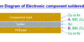
For OSP-finished boards: Based on the shear test results for SAC305 solder joints, one reflow cycle and two reflow cycles appear to have little effect on solder joint strength. However, after high-temperature aging, the solder joint strength drops noticeably. One possible explanation is the evolution of the IMC layer. Initially, the copper-based OSP finish forms Cu₆Sn₅, which is generally considered a favorable IMC. As aging continues, copper gradually diffuses toward the interface and reacts with the existing IMC, causing it to transform into Cu₃Sn, which is generally more brittle.
Cu₆Sn₅ + 9Cu → 5Cu₃Sn
In other words, the solder joint strength of copper-based finishes can deteriorate over time. This means products using OSP-finished PCBs may become more susceptible to solder joint failures the longer they remain in the field.
For ENIG-finished boards: Based on the shear test results for SAC305 solder joints, there is no significant difference in fracture energy (solder joint strength) among the three conditions: one reflow cycle, two reflow cycles, and reflow followed by aging at 150°C for 200 hours. This may be related to the fact that the nickel-tin IMC, Ni₃Sn₄, does not undergo the same type of further degradation. However, keep in mind that all types of IMC continue to grow over time, and an excessively thick IMC layer can weaken solder joints. For more details, you can refer to my previous YouTube video about IMC.
From this perspective, once ENIG-finished PCBs have passed the required design reliability and quality validation, products using this finish may have a lower risk of field failures over time. This assumes, of course, that PCB manufacturing defects such as black pad are not present.
Please note that the original experiment did not include SMD (Solder Mask Defined) and NSMD (Non-Solder Mask Defined) pad designs as test variables. Based on my own experience, different pad designs can have a significant impact on BGA solder joint strength. Workingbear’s previous company also conducted experiments on this subject. For more details, see the following articles:
Other factors, including solder paste alloy composition, flux formulation, reflow profile, IMC thickness, and test methods, can also affect solder joint strength.
Here is the big question: Since this article shows that OSP-finished PCBs can provide stronger solder joints than ENIG-finished PCBs, does that mean your company should switch all its products to OSP? Workingbear would like to hear what you think!




Leave a Reply