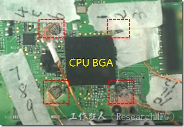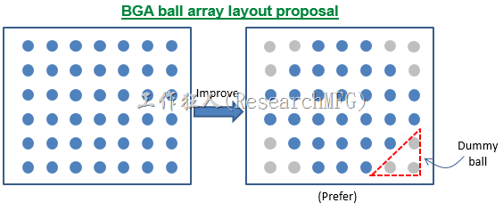
In the previous article, WorkingBear talked about how to improve the adhesion of PCA to resist the impact of stress. Today, We will move on to another topic: “How to increase the ability of components or circuit boards to resist stress?” Because the maximum impact of stress on solder cracking is board bending, we only need to think about how to enhance the product’s ability to resist the stress impact caused by board bending to solve the problem of solder cracking.
How to increasing the ability of components to resist stress?
1. Increase the stiffness of the PCB to resist stress and avoid the impact stress of board bending
Mentioning the stress resistance, we must talk about the “stiffness” issue of PCB. If the stiffness of the PCB is strong enough, it can reduce the board bending caused by stress, and board bending deformation is an important factor in BGA solder cracking. (Please note that WorkingBear does not fully understand the issue of PCB materials, and this content may contain errors. Please refer to it with caution.)
First, we must understand what “stiffness” means.
In the simplest terms, stiffness is the ability of the material structure to resist the deformation caused by stress. Before explaining stiffness, we must also explain the difference between elastic modulus and stiffness to prevent confusion.
“Elastic modulus” refers to a material’s ability to resist elastic deformation (non-permanent deformation) when a force is applied to it. It is a mathematical parameter that describes the relationship between stress (the force applied per unit area) and strain (the resulting deformation per unit length). The formula for elastic modulus is E = stress/strain. Elastic modulus is an important material property used to characterize and compare the mechanical behavior of different materials under stress.
“Stiffness” refers to the ability of a material or structure to resist deformation when a force is applied to it. It is defined as the ratio of the force applied to the resulting deformation. The formula for stiffness is K = F/D, where K is the stiffness, F is the force applied, and D is the resulting deformation. Stiffness is an important characteristic of structures, and it can vary depending on the geometry, material properties, and loading conditions. For example, the same material can produce different stiffness when used in different structural configurations, such as H-shaped steel or T-shaped steel. Additionally, stiffness can vary depending on the location and direction of the applied force.
k = AE/L, k=stiffness, A=cross-sectional area, E=elastic modulus (Young’s modulus), L=length of the object
As WorkingBear understands, the following factors will affect the stiffness of PCB:
- The stack-up of PCB material will affect its stiffness
When the engineer completes the PCB layout design, they typically already defined the functions of each layer of the PCB, such as top signal, Vcc, GND, bottom signal, and so on. However, different PCB manufacturers may choose different stack-up designs for their PCB processes, and these designs may result in various stress structures, affecting the PCB’s ability to resist stress bending differently. For example, for a four-layer PCB, the stack-up design can be either [1+2+1] or [2+2]. PCBs with more layers will have even more options for stack-up design. Additionally, different stack-up designs can also affect the electromagnetic compatibility (EMC) capability. Therefore, if a layout engineer can manage PCB processes, it is strongly recommended that they define the stack-up and thickness of each layer on the drawing or discuss with the PCB manufacturer to avoid differences in stack-up design that may affect the performance of the PCB when seeking a secondary supplier.
- Different PP & CCL will also affect PCB stiffness. Tg value is the key.
When choosing PCB materials from different manufacturers or models of PP (Prepreg) / CCL (Copper Clad Laminate), it will also affect the stiffness of PCB, especially when choosing materials with various Tg value. Most of the lead-free PCBs use mid-Tg materials with a Tg value of 150, while high-Tg materials are generally above Tg170, indicating that their temperature resistance ability is higher, and therefore their stiffness is also better.
Recommended article: Introduction to the structure and function of PCB materials.
Article series :
- Why BGA soldering ball always crack(1)? Stress > bonding-force
- Why BGA soldering ball always crack(2)? The composition of PCBA bonding-force
- Why BGA soldering ball always crack(5)? Increase the contact area of solder to increase its strength
- Why BGA soldering ball always crack(6)? The recommendation of BGA pad design from Workingbear
- Why BGA soldering ball always crack(7)? The Bonding force between solder pad of copper foil and PCB substrate
- Why BGA soldering ball always crack(9)? Increase the resistance of components to stress
- Why BGA soldering ball always crack(10)? Reduce the impact of PCB bending through the mechanism design change
- Why BGA soldering ball always crack(11)? Stress is the Biggest Culprit in Causing BGA Solder Joint Cracks
- Why BGA soldering ball always crack(12)? Manufacturing Processes That May Generate Significant Stress
- Why BGA soldering ball always crack(13)? Usage Environment is the Biggest Challenge of Stress Sources
Related article:
Increase solder paste volume will improve the MLCC capacitor broken?


Leave a Reply