
Is that possible for both solder joint bridging and open solder joint defect occur in the same BGA (Ball Grid Array) or CSP (Chip Scale Package) device?
It is rare to observe both solder joint bridging and open solder joint defects simultaneously in a BGA device under normal circumstances, but it is still possible. In cases where the BGA substrate and PCB exhibit a significant deviation in CTE (Coefficient of Thermal Expansion), the BGA substrate may deform with a concave smile-up curve, while the PCB may deform with a convex cry-down curve due to longer TAL (Time Above Liquidus) or significant temperature variation between the upper and lower heaters in the reflow oven.
It is possible to observe both solder joint bridging and open solder joint defects in the same BGA device if the smile-up and cry-down curves occur simultaneously. The image below shows a BGA substrate with a smile-up curve and a PCB with a cry-down curve. The balls located in the center of the BGA are almost touching each other due to being squeezed and flattened, while the balls located at both ends of the BGA have been elongated.

There are three possible solutions to address this kind of issue:
-
Minimizing the temperature gradient during reflow by adjusting the heating profile of the reflow oven.
- Pre-heating the BGA device prior to assembly to eliminate any residual stress.
-
Using a substrate material with a higher Tg (glass transition temperature) to improve its thermal stability.
Additionally, there are various factors that can lead to open solder joints in BGA devices:
-
Oxidation of PCB solder pads or BGA solder balls, which can result in similar symptoms to those of wetted PCB or BGA.
-
Expired solder paste or insufficient solder paste volume during printing.
-
Poorly configured reflow temperature profiles, such as excessively rapid temperature increases, which can cause smile-up and cry-down curve deformation in both the PCB and BGA.
-
PCB design issues, particularly via-in-pad or call via-on-pad designs on the BGA pads without filling, can make it difficult to control solder volume and lead to insufficient solder due to the solder flowing into the via during reflow. Via-in-pad designs can also result in voids or bubbles inside the BGA ball due to via outgassing and swelled BGA balls.
-
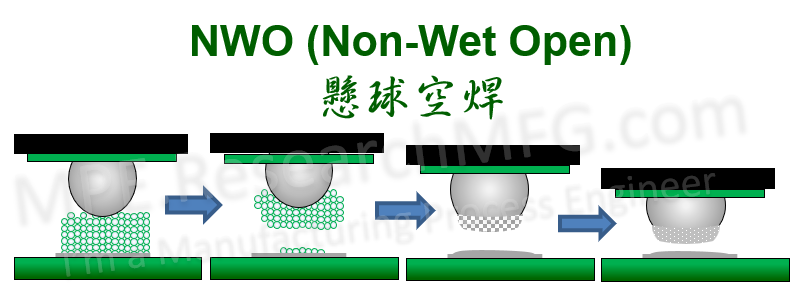
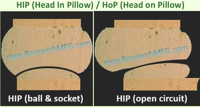
HIP (Head-In-Pillow) / HoP (Head on Pillow) or NWO (Non-Wet Open) defects, which typically occur when the BGA substrate or PCB becomes deformed during poor reflow heating processes. In such cases, when the solder paste melts in the reflow zone, the BGA solder ball does not touch the liquid solder due to board warpage. During the cooling zone, the deformed PCB or BGA substrate returns to its original position, but the melted solder solidifies. When the solder on the PCB pad and BGA ball come into contact, the phenomenon of two balls is observed.

There are several methods available for analyzing open solder joints in BGA balls:
1. Microscopy: This method involves using a microscope to inspect the outer row of BGA solder balls. In some cases, a fiberscope may be used to inspect the second row of balls.
2. X-ray Inspection: X-ray inspection can detect solder shorts and is also useful for detecting open solder joints. For optimal results, a 2.5D or 3D CT X-ray can be used to inspect the BGA from multiple angles to identify potential HIP/HoP issues.
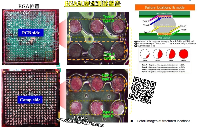
3. Red Dye Penetration Test: Red dye is applied to the BGA after a non-destructive inspection solution has been used, as this method is destructive. The red dye can reveal any solder shorts or open solder joints.
4. Cross-sectioning or call Micro-sectioning: This is a destructive testing method that focuses on a specific position to check for open solder joints, solder shorts, and Intermetallic Compounds (IMCs).
Related articles:


Leave a Reply