Choosing between RSS (Ramp-Soak-Spike) and RTS (Ramp-To-Spike) for the reflow temperature profile in the SMT (Surface Mount Technology) process has been a constant dilemma for many engineers. Some face pressure from higher-ups to opt for RTS due to cost-saving benefits, while Workingbear personal uncertainties about its soldering quality linger.
The solution between them isn’t complicated, but first, let’s comprehend what RSS and RTS temperature profiles entail. Only by delving into the purposes and limitations of these profiles can you select the reflow temperature profile that aligns with your product. In essence, both temperature profiles have their merits and drawbacks, so the choice depends on the specific circumstances.
In this article, we’ll attempt to outline the characteristics of RSS and RTS reflow temperature profiles, along with the encountered challenges. It aims to provide a directional guide for making a choice. It’s important to note that the content presented is not a definitive answer but rather a personal perspective for your consideration. Please reflect carefully before making decisions.
RSS: Ramp-Soak-Spike in Reflow Soldering

In the reflow soldering process, the “Soak zone” is essentially the “heat absorption area” or “active zone.” The primary purpose of setting this constant temperature zone before reflow is to ensure that all large-size grounded copper foils and small-size ungrounded copper foils on the PCB surface, as well as solder pads of different sizes and materials, reach the same temperature before entering the reflow zone. This ensures optimal soldering effects during reflow. This is why we suggest calling this zone as “heat absorption zone,” allowing all objects entering the reflow to absorb enough heat to reach a consistent temperature. It’s somewhat like waiting for a while before marching into battle, gathering all scattered soldiers together. Then, with a unified effort, they charge forward. Otherwise, if everyone is scattered, they are easily defeated.
If the temperatures are uneven between different pads and different components when entering reflow (“temperature difference △T” is too large), soldering defects may occur, such as:
-
Uneven Temperatures in the Reflow Zone can Lead to SMD Component Assembly Issues:
If the temperatures are inconsistent between different components when Surface Mount Device (SMD) components enter the reflow zone, problems such as insufficient soldering (due to low temperatures) or burning of components (due to excessively high temperatures or prolonged exposure) may occur.
-
Mismatched Temperatures on Different PCB Pads for the Same Component can Cause Tombstoning:
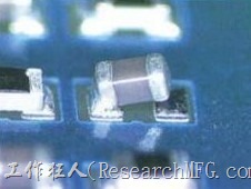
When the same component on different solder pads fail to reach the same temperature before entering the reflow zone, the tombstone effect may occur. In the case of Ball Grid Array (BGA) components, issues like Head on Pillow (HoP/HIP) or Non-Wet Open (NWO) become more likely.
-
Temperature Discrepancies Between Component Pins and Corresponding Pads can Result in Soldering Defects:
If the temperature of component pins and their corresponding pads does not synchronize before entering the reflow zone, problems such as solder being drawn entirely to the pins (solder bridging or “wicking effect soldering”) or pins not adhering to solder (non-wetting) may arise.
In the commonly used reflow soldering process with SAC305 lead-free solder paste, the temperature in the constant temperature (soak) zone is usually maintained within the range of 170±10°C. It is crucial to keep this temperature below the melting point of the solder paste. This temperature phase serves two main purposes: firstly, it allows for the gathering of a large number of components (ensuring temperature consistency), and secondly, it enables the flux in the solder paste to start its role in removing oxides.
Disadvantages of Ramp-Soak-Spike (RSS)
It’s important to note that within this isothermal zone’s temperature gradient, the solvents originally added to the flux of the solder paste will accelerate evaporation as the temperature rises. While activators will initiate and start removing oxides from the surface of the solder joint, the optimal time to eliminate oxides is when the solder paste has just begun to melt. This is because the molten solder paste can use liquid tin to push the oxides away to the edges or outside of the entire solder joint during the soldering process. This prevents oxide residues from lingering inside the joint, causing soldering defects.
Based on the characteristics of the solder paste flux, theoretically, the temperature in this isothermal zone should not be too high or prolonged. Otherwise, the flux will dry up rapidly, hindering its performance when assisting in solder melting. The amount of flux residue entering the reflow zone directly affects the quality of the solder joint. This is a crucial point that many engineers often overlook. For this reason, all solder paste manufacturers will advise against setting the temperature in the isothermal zone too high or for too long. Moreover, the heating rate after leaving the isothermal zone should not be too low, and it’s not recommended to be below 1°C/Sec. The goal is to retain as much flux as possible when entering the reflow zone. If the flux disappears significantly before entering the reflow zone, the likelihood of defects such as non-wetting, cold solder, and HoP/HIP or NWO will increase significantly. However, if the second heating rate is too fast, it can lead to the problem of “solder splatter.” Imagine frying fish in a pan with excessively high heat; reducing the second heating rate appropriately can help minimize solder splatter. So, setting the slope is essentially a narrow window.
Furthermore, the first heating rate in the preheating zone should not be too fast, ideally not exceeding 3°C/Sec. This is because the flux in the solder paste contains rosin, with a softening point roughly between 90°C and 110°C. If the preheating rate is too fast, reaching the softening point of rosin quickly without allowing the solvent to evaporate will reduce the viscosity of the solder paste. This can ultimately lead to solder paste collapse, with milder cases resulting in more solder beads and severe cases causing solder shorts.
RTS: Ramp-To-Spike – Skipping the Soak Zone for Efficient Reflow

The RTS (Ram-To-Spike) reflow profile, also known as the “mountain” or “inclined-rise” profile, is designed with the primary goal of aligning with the characteristics of flux. Considering the issues discussed earlier regarding the Soak Zone in the RSS profile, which accelerates flux evaporation and drying, the RTS profile suggests a solution. Instead of having a Soak Zone, or by transforming it into a gradual heating zone, we can significantly reduce the rate of flux evaporation. This modification increases the residual flux during reflow, enhancing soldering performance. Moreover, it improves solder joint quality during reflow (if this explanation is unclear, please revisit the beginning of the article and review the characteristics of the RSS reflow profile). Additionally, adopting the RTS profile can shorten the overall reflow time, leading to energy savings without compromising soldering effectiveness. It’s like hitting two birds with one stone!
While the concept is ideal, the reality can be harsh. Eliminating the “Soak Zone” means that the temperature difference, denoted as ΔT, might increase. However, if we can effectively control the ΔT on all solder pads and component leads on the PCB before entering the reflow temperature, the RTS reflow profile can be a viable and efficient option!
Which PCBA Are Suitable for the RTS Reflow Profile?
With the advancement of technology, there is an increasing number of reflow ovens equipped with efficient heat compensation capabilities. Particularly, those with more than 10 heating zones are no longer plagued by temperature variations due to the density of PCBAs in the chain of reflow ovens or the quantity of electronic components on them. This is highly beneficial for ovens adopting RTS profile, as the initial design of RSS profile faced a significant limitation—the inability of the reflow oven’s heat efficiency to keep up. Therefore, having a reflow oven with efficient heat compensation is a crucial prerequisite for adopting RTS.
Furthermore, if the components on the PCBA are simple, without complex parts such as BGAs or large components that are particularly challenging or slow to heat, meaning the temperatures between components can easily achieve uniformity, it is recommended to use the RTS reflow profile.
However, if your PCB is too large or has too many layers, even if the components are simple, it is recommended to measure the temperature of key locations using a profile board before deciding whether to adopt an RTS profile. When measuring with a profile board, be sure to include solder joints that connect to large grounding copper foils and are mostly covered by solder mask, as well as independent solder pads without connections to large copper foils. Once feasibility is confirmed, conduct a small trial run to ensure that solder defects are within manageable limits before moving on to mass production. Only after observing several batches without issues can you confidently switch the production line to RTS reflow profiles.
It’s a common scenario where engineers, without a deep understanding, choose the RTS profile simply because it’s the boss’s preference, and initial trial runs show no major problems. However, issues often emerge during large-scale production. This typically occurs because, during the trial run, the PCBs in the reflow oven had more space. In mass production, as the PCB spacing decreases and the reflow oven’s energy supply falls short, non-wetting issues can arise, especially on solder pads connected to large ground copper foils.
Now you should have a clear understanding of whether your reflow temperature profile should be set as RSS or RTS!
Compromise Solution between RSS and RTS

If you find that the RTS profile requirements are challenging to meet during trial run but you’re keen on using RTS, you might want to explore a middle-ground solution that combines elements of both RTS and RSS. Stick to the temperature profile of RSS but modify the “soak zone” to a more gradual incline. Of course, it’s crucial to ensure that the temperature difference between the board and components remains within an acceptable range.
Related Posts:


Leave a Reply