In the electronic devices we use daily—such as remote controls, smartphones, refrigerators, TVs, air conditioners, and computers—there is a crucial component called the Printed Circuit Board (PCB). The name comes from the way its electrical circuits are formed, similar to early book printing. Some also refer to it as a Printed Wire Board (PWB).
Simply put, a PCB acts as the foundation of an electronic device, connecting all the electronic components into a single network so they can work together efficiently.
Workingbear likes to compare a PCB to the chassis of a car, where all the components are mounted and function as a system. However, another way to think about a PCB is as a city layout with pre-built roads, ready for different buildings and facilities to be placed at designated locations. Once everything is in place and functional, the developed city represents a PCBA (Printed Circuit Board Assembly)—commonly referred to as an assembled circuit board.
A PCB is typically a rigid board with a thickness of 1.0mm to 1.6mm, though its thickness can vary based on design needs. Some PCBs are even thinner or thicker, while others are designed to be flexible (FPCB – Flexible Printed Circuit Board), allowing them to bend or fold. For more advanced applications, rigid-flex boards combine both rigid and flexible sections in a single design.
On top of the PCB, there is one or more layers of conductive metal—usually copper—which forms an intricate network of electrical pathways. This network is like the streets of a city, enabling different electronic components to communicate and work together.
These components can be passive elements like resistors, capacitors, and inductors, or active components like transistors and integrated circuits (ICs). Each has its own function. When connected through the PCB’s copper pathways, they form a complete electrical circuit, just like how buildings in a city are connected by roads and infrastructure. Once power is supplied, the circuit begins operating as designed.
In summary, the PCB organizes and connects all the electronic components inside a device, allowing them to work together to perform functions like playing music, displaying images, or transmitting messages. This is the fundamental role of a PCB in electronics.
Currently, the most common types of circuit boards on the market fall into three main categories:
Rigid Printed Circuit Board (Rigid PCB) – Traditional solid boards.
 The main reason PCBs are categorized this way is that most PCB manufacturers focus on producing rigid PCBs, which also have the highest market demand. Besides transmitting electrical signals, PCBs serve as a mechanical support for electronic components. These components are typically soldered onto the PCB, but solder is not flexible and cannot withstand significant bending or deformation. Excessive stress can cause solder joints to crack or even damage the electronic components themselves. This is why Workingbear has written multiple articles discussing solder joint cracking issues and possible solutions.
Because the majority of printed circuit boards are rigid PCBs, people often refer to PCBs as a general term for rigid circuit boards.
A rigid PCB consists of an insulating substrate, usually made of fiberglass (FR4), which provides strength and rigidity. Copper foil is then laminated onto this substrate to form single-layer or multi-layer circuit boards.
Flexible Printed Circuit Board (Flexible PCB, FPCB, or FPC) – Bendable, lightweight boards.
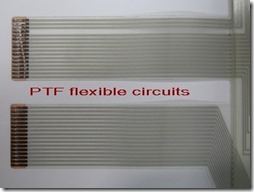
 A Flexible Printed Circuit Board (FPCB or FPC) is made by laminating a conductive copper layer onto a polymer film, which is somewhat similar in texture to a thin plastic bag.
The biggest advantage of FPCs is their flexibility and bendability, making them ideal for compact spaces where a single rigid PCB cannot accommodate the entire design.
Some products require stacking multiple PCBs on top of each other, and an FPC can be used to connect them. Others use FPCs to reduce material costs by enabling long-distance signal connections between different PCBs. In short, the primary purpose of an FPC is to connect separate PCBs and facilitate signal transmission.
However, due to its flexible nature, an FPC cannot support heavy electronic components for soldering. To solve this, engineers developed a solution: attaching a stiffener underneath the FPC to reinforce certain areas. This prevents excessive bending in critical sections, which reduces the risk of solder joint cracking.
Compared to rigid PCBs, FPCs are not ideal for complex circuits or high-precision soldering of small electronic components. If you’re interested in learning more, check out this article:
🔗 Recommended Reading: What Is FPC (Flexible Printed Circuit Board)?
Rigid-Flex PCB – A hybrid of rigid and flexible materials.
 The primary purpose of FPCs is to connect different rigid PCBs. To secure an FPC to a rigid PCB, manufacturers typically use connectors or HotBar soldering, which directly bonds the FPC to the rigid board. However, this method requires dedicated space on the rigid PCB for connectors or soldering pads. As electronic devices become smaller and component density increases, this unused space becomes a major design constraint.
To solve this problem, engineers developed Rigid-Flex PCBs, where flexible and rigid sections are integrated into a single unit. This design eliminates the need for separate connectors or soldering areas, freeing up space for other components.
In theory, Rigid-Flex PCBs offer several advantages, including:
✅ Space-saving design
✅ Reduced signal transmission loss
✅ Simplified assembly process, lowering labor costs
However, real-world production comes with challenges:
❌ Higher manufacturing costs—Rigid-Flex PCBs are more expensive than using separate rigid PCBs + connectors + FPCs.
❌ More complex SMT assembly—The flexible section requires reflow carriers/templates to support it during reflow soldering.
❌ Difficult repairs—Fixing or modifying a Rigid-Flex PCB is more complicated than a standard rigid PCB.
Because of these factors, Rigid-Flex PCBs are usually reserved for high-end products or applications with strict design constraints. While they provide a valuable design option, they are not always the most cost-effective solution.
🔗 Recommended Reading: What Is a Rigid-Flex PCB?
Other PCB Classification Methods
Besides categorizing PCBs by their rigidity, they can also be classified based on:
✔ Surface Finishing Method:
- OSP (Organic Solderability Preservative)
- Electroplated Gold
- ENIG (Electroless Nickel Immersion Gold)
- HASL (Hot Air Solder Leveling)
- Immersion Tin (ImSn)
- Immersion Silver (ImAg)
✔ Application Type:
- Computer motherboards
- Communication boards
- Automotive PCBs
- Consumer electronics PCBs
- IC Substrates
✔ Number of Circuit Layers:
- Single-layer PCBs
- Double-layer PCBs
- Multi-layer PCBs
✔ Base Material:
- Plastic-based PCBs
- Ceramic-based PCBs
- Metal-core PCBs (Aluminum-core, Copper-core, etc.)
✔ Via Structure:
- Through-Hole PCBs (PTH – Plating-Through-Hole boards)
- Microvia PCBs
- Blind Via PCBs
- High-Density Interconnect (HDI) PCBs


Leave a Reply