 One day, my manager asked me a question: “Will changing the components from SMDs (Surface Mount Devices) to THDs (Through Hole Devices) and using the PIH (Paste-In-Hole) process affect the process and design?”
I later realized that the question aimed to prevent damage to connector components due to customers using excessive force.
Sometimes, Paste-In-Hole (PIH) is also referred to as Pin-In-Paste (PIP).
First, when considering traditional components inserted using the PIH process, there are several design considerations:
-
It is preferable to package PIH components in tape & reel format for SMT machine mounting purpose, or at the very least, use a hard tray.
-
PIH component materials must withstand the high temperatures of the SMT reflow process. Generally, PIH components are placed on the second side of reflow. In the context of the current lead-free reflow process, these components should be able to withstand temperatures of 260°C for more than 10 seconds.
-
The pins of PIH components should not have kinks or overly tight fits in their design. Otherwise, placing these components on circuit boards becomes challenging. If manual placement is necessary, it might involve excessive force, leading to potential circuit board vibrations and, consequently, the risk of misalignment or detachment of mounted components.

-
The top surface of PIH components should be flat and free from voids to enable the SMT machine’s nozzle to pick them up easily. Additionally, it’s a good practice to apply tape to the surface of PIH components to prevent air leakage.
-
A 0.2mm gap or standoff should be included where the pins of the PIH component connect with the circuit board. This design feature serves to prevent both the siphon effect and solder overflow. These issues could lead to unpredictable solder splatters, affecting product quality.
-
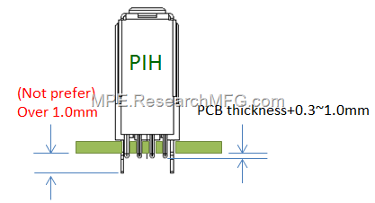
It’s recommended that the length of the pins on PIH components be 0.3 to 1.0mm higher than the thickness of the PCB. Since most parts using the PIH process are utilized in external connectors, pins higher than 1.0mm could disrupt the pick-and-place operation, while pins less than 0.3mm might result in insufficient solder. For smaller PIH components, the PCB’s extended height should also be smaller.

The impact of substituting the conventional SMD parts with PIH parts or SMD+PIH parts on process and design is summarized as follows:
-
Working Hour: There is no significant difference between the operation time of these two types of components.
-
Cost: PIH components might cost more than SMD components due to having more pins for through –hole connectors.
-
SMT Part Space: It’s advisable to keep at least 1.5mm space between PIH components. On the other hand, SMD components can be placed closer together, even at 1.0mm or 0.5mm spacing. This extra space for PIH parts is needed because their pins are more prone to bending, and they require larger holes. The recommended pin diameter to hole diameter ratio is generally 0.5-0.8, and due to potential mounting variations, more space is necessary.
-
Rework: Repairing or replacing PIH components is generally more complex compared to SMD components. This is because the solder inside each through-hole must be removed for PIH component replacement. While replacing the entire component can be considered, reworking PIH parts generally involves more intricate procedures.
-
Space Usage Rate of Circuit Board: Because there are pins in the back of PIH parts, the available space is relatively less on circuit board.
-
Solder Filling Issues: As per IPC-610 standards, the solder filling for the pins of a component inside the through-hole should be over 75%. However, certain restrictions might lead to issues with regular solder paste application. This could require additional solder paste in some cases.
In fact, the solder joint strength of PIH process is larger than conventional SMD process, because the product can be processed by more insertions and extractions. According to the experience, about 1.5 times of strength is enhanced based on the number of pins and the size of each pin.
Related article:


Leave a Reply