A while back, a netizen asked how the Router de-panel machine cuts PCB panels and whether there’s a need to reserve board edges (break-away) for the Router machine in PCB design. Upon careful consideration, I thought my previous answer might have been too brief. So, in this post, I’ve decided to delve deeper into these questions.
If you’re still unsure why PCBs are panelized before SMT and PCB assembly then de-paneling it into individual PCBA after assembly or what need to reserve board edges for Router machines in PCB design, please refer to the article titled “Why is Panelization and Break-away Tab Necessary in PCB Manufacturing, then De-paneling after PCBA is Completed?“
Question 1: Is it necessary to include V-cut grooves or similar features when using a Router de-panel machine to separate PCB panels into individual boards?
Answer 1: Before addressing this question, it’s important to understand why some PCBs require reserving board edges. This is because the automated assembly processes for PCBA (Printed Circuit Board Assembly) use mechanical devices like chains for transporting semi-finished PCB assemblies. Visualize or observe how PCB moves from solder paste printing stage to the Pick & Place machine and through the reflow oven on an SMT production line. These conveying mechanisms almost always employ chains and are positioned at the left and right edges of the PCB’s path. This is one of the primary reasons PCBs need board edges because, with current mechanical conveyor technology, electronic components are not allowed to be placed in areas where chains are used. Additionally, components must be positioned a certain distance away from the chain’s positions to prevent them from falling off or affecting their reliability. Another device that utilizes board edges is the magazine rack, which stores assembled PCBs using multiple slot-like slots.
Therefore, if your company’s PCB assembly does not require the use of chains for PCB transport and does not use a magazine rack, then your PCBs may not need to design board edges on it. However, this scenario seems somewhat impractical. The opportunity to save board edges usually arises when there is sufficient space on the board, and all electronic components can be arranged inward to avoid chain positions. In such cases, there may be no need for board edges, but special requirements like hole positioning may still need to be considered for certain pick and placement machines.
To answer whether V-cut grooves or similar features are needed when using a Router de-panel machine to cut PCB panels, it’s not necessary to reserve V-cut grooves. Router de-panel machines use computer-defined paths and milling cutters for cutting panels, and they do not rely on V-cut grooves for positioning. However, you should prepare a fixture for the PCBA to ensure that the placement is consistent each time while the PCB is cut, preventing any misalignment by the Router machine.
Question 2: What are the requirements for the PCBA fixture when using a Router de-panel machine?
Answer2: When using a Router de-panel machine to separate PCBA, a fixture is required to ensure consistency in the cutting position for each operation. The Router machine uses a cutter head similar to a milling cutter, and the depth of the cutter head must be greater than the thickness of the printed circuit board PCB). Therefore, it is advisable to reserve some pre-milled space along the cutting path of the PCB, allowing the milling cutter to be placed at a certain depth before starting the cutting process. Additionally, the fixture must avoid the milling cutter’s path to prevent direct contact between the cutter and the fixture, which could cause damage to the fixture or cutter.
Furthermore, during the cutting and separation process, each individual board must be secured. This is essential to prevent issues such as boards dropping into the fixture when all the ribs connecting the PCBA have been cut. Another reason for securing the individual PCBAs is that when the milling cutter moves, it generates a centrifugal force that can cause boards to be thrown off or deviate from the cutter’s path, potentially resulting in damaged boards.
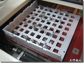
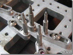
Since most printed circuit boards are designed with screw holes or other circular holes for positioning purposes, most fixtures use cylindrical locating pins to pass through these holes and secure the individual boards. If it’s not possible to design circular holes on the individual boards, you can consider using the external frame of the circuit board for fixation. However, you must clearly specify and define the dimensions and tolerances of the circuit board’s external frame, and a minimum of three points is typically required to securely hold the circuit board.


Left Image: A universal fixture used with a Router cutting machine, featuring multiple locating pins for securing the circuit board.
Right Image: A close-up view of the locating pins on the universal fixture for the Router cutting machine. The endpoint of the locating pin is tapered for easy insertion and removal of circuit boards.
Related Articles:


Leave a Reply